It has always been our intention to allow the plans to be used for building a commercial simulator. Purchasing a plan set allows you to build one throttle quadrant (or simulator when those plans become available). You may use that simulator for commercial purposes, e.g. for a museum. (note however that as we have no control over build quality we cannot accept any liability for accidents or injuries that may occur as a result).
Another bit of news is that it is now only possible to log in to the site with your USERNAME (so please don’t use your email address, you will be locked out). This is as part of our ongoing security processes. If you have any problems logging in or other questions, please contact myself through use of the Contact Form.
We are entering the next phase of our build having received all 200 SLS Nylon 3D printed components. It is exciting and most gratifying to see how everything just works straight out of the box. Components clip together effortlessly and work beautifully.
Morse Code Signalling Box showing perfect fit of parts and fine detail
In this example we are displaying the Morse Code Signalling Box assembly. Internally the electronics components, in this case 3-way rocker switches, slide in and work beautifully. The custom recreations of the position switches clip perfectly onto the M2013 switches.
Morse Code Signalling Box internal view of the rocker switches
The SLS Nylon PA2200 is incredibly strong, having a tensile strength of 48MPA and it can take up to 163degC. You can find the full specifications here.
Full set SLS Nylon components
Packaging
Our components have been printed in white, which will provide the best base for painting. The finish is slightly grainy and porous given the laser sintering technique. Hence we will be painting the objects with a resin base coating to give it a smooth finish. We will be trying out the XTC-3D product for this, which is readily available.
We will be coating our parts with XTC-3D to provide sealing and a smooth finish
Once the protype build is complete, we will be making all the components available through our shop on Shapeways.
We will be providing regular updates on the progress of the finishing and detailing of these parts. However the priority for now is to complete the DXF cutting patterns of the metalwork so that we can get those into manufacture. We have completed the 119 parts to be lasercut cut from 0.9mm aluminium sheet and have started on the 2mm sheet patterns. Only around 220 to go!
We have made steady progress over the last two weeks. The numbering, adding of metadata and checking of all components has been completed. This has allowed us to extract all the SLS Nylon 3D printed pieces and start generating the sheetmetal DXF files. We have also made good inroads into the development of a bespoke, low cost Malcolm Hood.
STL Files all generated
An STL file has been generated for each of the 200 SLS Nylon components. They have all been uploaded to Shapeways. These will be made available for purchase once the Prototype Build, Plans and Build Manual have been completed and proven correct and functional.
Generation of sheetmetal DXF files in progress
Our design contains 330 sheetmetal components as follows:
Aluminium Plate
0.9mm – 119 pieces
2.0mm – 134 pieces
3.0mm – 14 pieces
4.5mm – 44 pieces
Mild Steel Plate
2.5mm – 19 pieces
A DXF cutting file is created for each of these components. The file is layered to allow engraving of the part number and bend lines prior to cutting. The images below illustrate this for component number 08-03-04-15:
DXF File of the bracket
Bracket after bending
Bracket in position
Those components that require bending will also each have a bending diagram to provide guidance on the bend angle and direction.
Malcolm Hood Manufacture
Great news is that we have progressed significantly with the manufacture of a low cost Malcolm Hood. It will be made with 3mm Plexiglass. This is the standard for GA aircraft, hence should be suitable for use on a real aircraft. We have fabricated the necessary tooling and I hope to be able to report on further progress in my next post.
This week saw the completion of the wood components build, other than the covering which will be done when the internals are complete. There also remain a few bits and pieces related to the canopy but these will have to await the fabrication of the metal parts prior to gluing up.
Completed seat pan with fibreglass covered back
The seat pan was redesigned as I was not happy with the 6mm plywood seat back. It just looked too flimsy for what will need to be a very robust construction, so now the whole pan has been redone in 12mm plywood. I also incorporated a few tabs in the sides, bottom and front that now provide accurate assembly guidance points and additional strength.
Keyed construction assists simple assembly
The rear of the seat requires careful filing and sanding to incorporate the correct angle offsets. Here a 12″ sanding disk is a heaven sent. The rear supports provide the correct angles when gluing it up.
Seat back weighed down into rear supports while gluing up
Glued up seat frame prior to inserting back
Seat assembly completed
The seat back was then covered with fibreglass to provide additional strength and durability.
Seat back fibreglassed and front brackets installed
Bottom brackets installed
Seat test fit in the fuselage
Caroline demonstrating correct stick and rudder posture
Rear of seat being fibreglassed
The balance of the work consisted of the gluing up of Frame 9 and then finishing the related intercostals. The antenna mount which doubles as the seat belt harness anchor point was also installed.
Gluing up Frame 9
Antenna mount assembled and positioned
All frames and intercostals in place
That concludes the building for the time being. We need to finish off the numbering and application of metadata for the metal and 3D printed nylon parts before we can generate their cutting, bending and printing files and drawings. There are still 800 to go out of the 2000 or so, so all shoulders to the wheel to try finish that in the coming week! It is soooo much more fun to build 🙂
It’s been a week of hard work but I am amazed at how well everything has come together. I set out to design something that could give the pleasure of building a life size model of the Spitfire Mk.IX, as one would a small scale model plane out of a kit. I am happy to say that that was exactly the experience!
A lot of the time spent was simply waiting for the epoxy glue to harden, which could take anywhere between 12 and 18 hours. If I had unlimited workspace I could have done a lot more things in parallel and things would have gone even faster still. However I want the prototype to be built in a home workshop in order to experience the same potential problems customers may have.
The parts fit together beautifully. It was a delight to be able to simply drop the screws in place for the instrument panel in order to set the distances correctly for the panel supports. The translation from the 3D Cad model to the cutting patterns has gone extremely well. I am preparing assembly drawings as I proceed, picking up on pertinent points to be noted in the Build Manual. So hopefully that will be nearly ready for publication when the prototype build has been completed.
We have captured the weeks build on a time lapse camera and has resulted 1,5 minutes of video 🙂 You can check it out here:
The intercostals remain to be placed which I will do over the weekend, except for Frame 9 which will only be placed once the rudder pedals are positioned. Other than the seat, the door frame and the canopy supports that just about concludes the wood part of the build. Now we will focus on getting the rest of the numbering and checking done (900 to go out of a total of 2000 odd components!).
And then we start preparing the platework cutting and bending patterns. In the meantime we can make aeroplane noises while sitting in the cockpit!
CNC Lab have done a stunning job of the routing and we were able to collect all of it yesterday.
Who thought you couldn’t fit a Spitfire Cockpit in a Landrover?!!
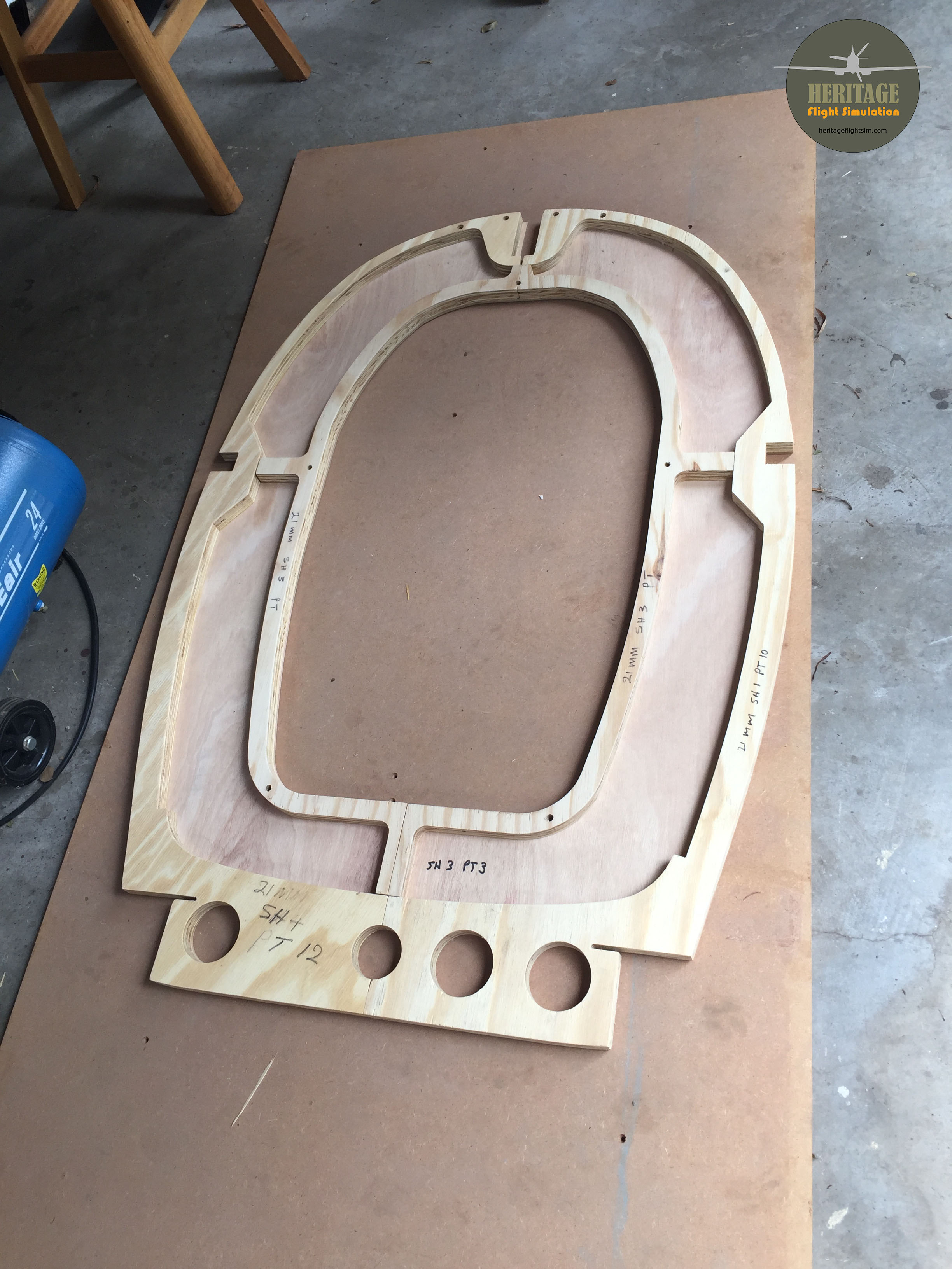
Fortunately all fitted very well into the Landy. The routing was all done with a 3mm bit, even the 21mm plywood. This has resulted in an excellent finish and very accurate drill hole sizes. It is wonderful what CNC Routing, laserjet cutting and 3D printing have done for the engineering industry and hobbyists particularly. It allows absolute accuracy of your bespoke components at reasonable cost. All it requires is accurate 3D modeling. And that is hopefully where we at Heritage Flight Simulation earn our keep!
Beautifully made main and flying instrument panel backings (will have an aluminium cover)
The parts are so accurate it is a doddle to do a quick dry fit of our first task, the cradle. Here my able assistant Caroline can be seen holding up Frame 11 (which originates from a previous test of waterjet cutting plywood) on the dry fit cradle bits.
The CNC routing is so accurate I cannot but be amazed at how beautifully everything lines up.
Anyway, that was yesterdays fun 🙂 Today we set up a time lapse video camera which hopefully will capture the build from start to finish at 5 minutes per frame. That should have us complete the build in about 10 minutes. Of video…heheh!
We have also started gluing up the box sides and wing spars of the cradle.
In what has been an amazing whirlwind of activity over the last just under 4 months, FlyingIron Simulations have released their L.F.Mk.IXc Spitfire for X-Plane 11. You can find it here on their site (AUD$) or here on the X-Plane.org site (USD$)
The Heritage Flight Simulation Spitfire cockpit internals which were meticulously drafted over the last year and a half formed the basis of this masterpiece and probably cut down the development time by a few months. That said, Alex and Dan Kassabian, the two Sydney Australia based brothers who formed FlyingIron Simulations, have an astonishing track record in creating exceptional aircraft in an amazingly short span of time. Their fantastic P47N was created in something like 3 months. These guys just never sleep!
Alex is the master artist who took the cockpit internals and deftly reduced their polygon counts in order to create an aircraft that has very little impact on framerates. While we had a good commercial copy of a Mk.V model available to us, Alex decided to design the Mk.IX externals from scratch. The result has been nothing short of amazing. The textures applied to the aircraft exterior and interior have resulted in a thing of real beauty.
Spitfire Mk.IX in post 1947 SAAF livery
Dan is the coding and sound expert and built the flight model and all the custom aircraft systems. This has resulted in an aircraft which has an extreme level of realism. The aircraft has been exhaustively tested in the last month and is running to the manufacturers numbers. The roar of the Merlin (you can chose between a 66 and 70) is something to experience!
The aircraft was designed from the outset to be VR optimised and utilise all the latest effects in X-Plane 11.3 All the controls in the aircraft can be manipulated and have an effect on the operation of the airplane. I suggest you have a look at their link above to get the full gist of what they have achieved. Better yet, go purchase a copy. If you are in any way a Spitfire enthusiast, and I am assuming you are if you got this far in the article 😃, you owe it to yourself!
Why my interest in having an alternative to the great Spitfire Mk.IX simulation in DCS World, which, through VR, also puts you in the cockpit as if you were really there? The reason is twofold:
X-Plane allows you fly the aircraft anywhere in the world. You can explore the British Isles, practise your skills in Toronto or land in Darwin Australia. The Ortho scenery such as the TrueEarth Great Britain from ORBX is remarkable.
For museums wishing to run the HFS Spitfire Simulator on a commercial basis X-Plane is a lot less onerous than DCS World. It requires a once off professional licence for $750USD. In contrast, DCS World have quoted some EU250 per month for the same privilege.
Heritage Flight Simulation approached various X-Plane developers with a request to collaborate on creating an exceptionally realistic Spitfire Mk.IX simulation. Mostly the response was that their interest (and income) lay in General Aviation aircraft. It is a pity therefore that we have many incarnations of the Spitfire in X-Plane which have low levels of authenticity, most having been developed many years ago. Graphically and systems wise the X-Plane platform has advanced tremendously, more’s the pity that this has not been capitalised on by historical aircraft developers.
Fortunately though, when I approached Dan and Alex on the basis of their stunning P47N which had just been released at the time (get it here), they responded with enthusiasm. It has been a real pleasure working with these two exceptional young men. They have a real love for keeping aviation history alive and I am waiting with great anticipation on what they may have planned for their next effort!
After going out on enquiry with a sample cutting file to five different vendors we have selected CNC Lab in Randburg, South Africa to do our wood routing. We ordered the thirteen sheets of plywood and had it delivered directly to the CNC shop.
Plywood quality
A word on the quality of the plywood. There is a confusing array of grade classifications, including Brazilian, Malaysian/Chinese, Chilean, Finnish, Russian and Swedish amongst others. Here in South Africa we seem to use the Brazilian grade nomenclature. They have an excellent spec sheet which can be downloaded here:
This is an extract from their grading criteria page:
In brief, we use a combination of the letters to indicate quality front and back:
C+/C Face knots filled and repaired/reverse open knots
B/C No knots in face/open knots in reverse
B/B No knots face or back
We have stuck to using B/B grade Pine plywood. This gives a balance between quality and cost. According to the CNC shop we are using Birch ply gives a much better result with less ripping, but that comes at twice the price. Hence it will be fine for us to fill in the areas where some ripping has occurred – it all gets painted in the end anyway.
Routing
The routing started today and a number of the 6mm panels have been completed. This work will continue over the next few days and should be completed this week. Initial results are looking great.
Setting up of the CNC Router
Numbering
Together with the CNC shop we have decided that the easiest and cheapest way of numbering the parts will simply be to scribe the code on the part with a marker pen. We did consider laser engraving but for this it simply is not cost effective. (It is something we are considering on the metal parts that will be plasma cut, but that is simply because we have less control in that process).
The numbering is kept simple, giving the thickness of the ply, the drawing sheet number and the item number on the sheet. That’s easier than having to put in the actual Part Number
6mm parts with the numbering visibleExample of the sheets showing their item numbers unique to that specific sheet
With any luck we will be able to start gluing up over the weekend! 🙂
The Prototype build has officially begun! All the wooden cutting patterns have been completed and guidance drawings prepared. The cutting patterns are ready for any CNC Routing shop which can handle standard 2440mmx1220mm pine plywood sheets. The sheet thicknesses are as follows:
1 off 3mm
4 off 6mm
2 off 9mm
1 off 12mm
1 off 15mm
4 off 21mm
The cost for these sheets locally total around US$430. We have appointed a routing shop to do the work and the cutting will cost that again. So total cost, excluding epoxy glue, for the wood components will equate to some US$860. For that amount you will end up with the following:
The prepared wooden components should amount to around US$860
This does still exclude the thinner sheeting for covering the frame. Also note the bits at the back are only temporary jig supports for frames 12 and 12a. They get removed after gluing up so that once covered, the fuselage will look like this:
Covered fuselage rear
Covered fuselage profile
So this week we will be ordering the plywood from a local timber shop and have it delivered to the routing shop. Hopefully some of the routing will also start. We will provide pictures as we go along.
And yes, you guessed it, in the background we will continue numbering! 😅
The design collaboration with FlyingIron Simulations is going very well! They have been making great progress with their Spitfire Mk.IX for X-Plane 11! I have attached some screen-captures from my testwork, this is version 0.7Alpha. Even at this early stage the flight characteristics are superb, while the graphics model looks fantastic.
This model will work hand in hand with our simpit, so now there are two different simulators which will provide absolute realism and accuracy in VR; X-Plane and DCS World!