If a picture tells a thousand words, this must surely be it…


If a picture tells a thousand words, this must surely be it…
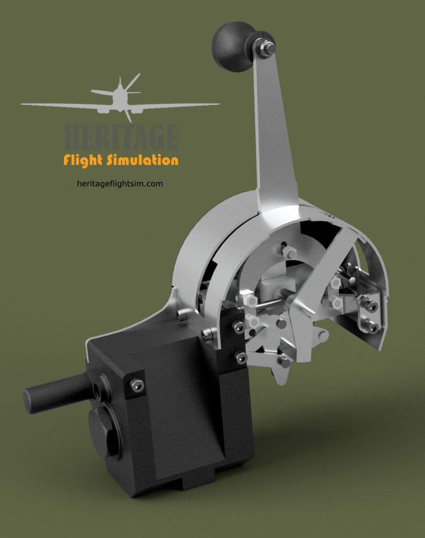
The Spitfire Chassis Control had, other than the name suggests, very little to do with it’s suspension. Instead it refers to the mechanism that activated the undercarriage. Perhaps the name was meant to convey its complexity, because complex it certainly is!
It is an array of hydraulic valves, pulleys and chains, which if by some stroke of dextrous genius the hapless pilot got right, would go clunking, whirring and rattling into place. Get it wrong and you would end up with a half retraction.
The manual describes the action required thus:
13. Undercarriage control.—The undercarriage selector lever (52) moves in a gated quadrant on the right-hand side of the cockpit. To raise the undercarriage the lever must be moved downwards and inwards to disengage it from the gate, and then moved forward smartly in one movement to the full extent of the quadrant.
When the undercarriage is locked up the lever will automatically spring into the forward gate.
Warning.—The lever must never be moved into either gate by hand as this will cut off the hydraulic pressure.
To lower the undercarriage the lever must be held forward for about two seconds, then pulled back in one movement to the full extent of the quadrant. When the undercarriage is locked down the lever will spring into the rear gate. An indicator in the quadrant shows DOWN, IDLE or UP depending on the position of the hydraulic valve. UP and DOWN should show only during the corresponding operation of the undercarriage and IDLE when the lever is in either gate. If, when the engine is not running, the indicator shows DOWN, it should return to IDLE when the engine is started; if it does not, probable failure of the hydraulic pump is indicated.
Our own design, which is progressing well, duplicates this action without the benefit of the hydraulics. We rely instead on a basic scissor spring action. It is set when the lever is moved downwards and inwards with a trigger plate. To move the lever inwards another spring (spring 2) needs to be compressed, as per the original mechanism. The lever is moved smartly forward, all in one movement, and then held in the foremost position for 8 seconds, the time in which the gear retracts. The lever is then released, causing it to snap outwards still under tension from spring 2. This activates the trigger release of spring 1 which snaps it back into the gate.
Quite simple. Heh heh…
You may of course elect to forego all that and do the build without the internals, having it operate simply as an up/down mechanism. But then, where’s the fun in that!


Today we installed the Radio Remote Control Box. The Type 4 (110J/71) control box operates the radio transceiver which is located in the rear of the fuselage. It has 4 preset channel buttons, labelled A, B, C and D. Next to each button is an indicator light showing which channel is active, The top button switches the remote off. At the bottom is a three way switch which is labelled “T-R-REM”. It toggles the three different modes of operation being Transceive, Receive and Remote.
In keeping with our philosophy to keep costs to a minimum, we have managed to utilise existing, readily obtainable components which closely match the look, function and size of the original.
Now to start on the Chassis Control Unit (gear lever)…bound to be an interesting challenge!

There is a wonderful little wartime publication called “Bag the Hun!”. Issued in April 1943 by the Air Ministry, it set out improve estimation of opening range and deflection in aerial gunnery.

Shooting down another aircraft from a platform that is moving and weaving across the sky itself is no mean task, as I have found out to my embarrassment on many an occasion with flight simulators such as DCS World. It requires much more than just instinct, and this little booklet was a great help to many pilots, including myself, to achieve greater success. If you do a little search on the internet you are sure to find it.
Which brings me to the main subject of this post. Not only do you need good visual calculating skills, but you also need good sighting equipment to be successful. Enter the Reflector Gun Sight Mark II, as fitted on our Spitfire Mk.IX Simulator.
We have recreated this beautiful optical piece in exacting detail and it offers full functionality within the simulator.

The gunsight has two adjusting rings, one for Range and the other to set the targets known wingspan in feet. In our case the rings do not adjust the optics but turn two independent potentiometers to provide a signal to the simulator. This required fairly intricate internals as can be seen from the exploded view below:

The gunsight also incorporates a dimming screen to better show the aiming reticule in bright light, this can be slid up or down as required. Microswitches indicate to the simulator what the position of the screen is.

The assembly fits into the simulator fuselage beautifully and complements the already impressive panel.

A few more pics for your viewing pleasure:


Just a reminder that there is still one day left to pick up the Spitfire Mk.IX Engine Hand Control plan set at the introductory price of $55. From tomorrow the price will revert to its normal $70.

The Instrument Panel is complete and the Six Pack is a thing of pride!
The panel consists of two main components; the main panel and the Blind Flying Panel, also known as the “Six Pack” as it contains the six elements most important for flying in cloud and dark.

In the top left of this panel you will find the Airspeed Indicator. Variations in this, up or down, will likely be the result of the nose being pushed under the horizon or pulled back, in that order. So if your airspeed is increasing and you haven’t touched the throttle, you are most likely heading for the ground!
Next up, working clockwise, is the Artificial Horizon. This is the prime indicator of where your nose is pointing and works on a gyroscope.
Then comes the Vertical Speed Indicator or VSI. Another indicator of whether you are going up or down but considerably more sensitive than the Altimeter which comes last.
The Turn and Slip Indicator is particularly important in gauging the steepness of your turn and making sure you balance elevator, ailerons and rudders in the turn. This to prevent slipping into the the turn or out of it, all of it important to gauge and maintain accuracy of a turn and keep navigation precise.
We then get the Gyro Compass Repeater. In itself it does not provide direction. You have to set it using your bet guess of what the magnetic compass is showing. You then turn the knob to show the same heading and for the next ten minutes or so it will provide a much more stable readout than you could get from the wildly swinging compass. You better check it again though in another ten minutes or so as it gradually creeps out of true.
Finally we have the altimeter. Important to gauge against the known (or suspected!) height of the ground. You set it by turning the knob when you’re on the ground to match the indicated altitude with the known ground altitude. It works of barometric pressure so will vary according to weather conditions and temperature.

Our panel accommodates nine switches, four rotary encoders and four potentiometers, accurately reflecting all the functionality of the Spitfire Mk.IX Instrument Panel.
Remember the gauges themselves are relatively cheap 3D Prints, each with a decal and acrylic glass cover. The working gauges will be found in your Virtual Reality headset 🙂
Speak to Spitfire builders and restorers about a particular Frame and they immediately can visualise what it is and where on the aircraft it is situated. So it is now with us here at Heritage Flight Simulation 🙂
So when I tell you about Frame 11 many of you will know that it is the substantial frame right behind the seat. It holds such items as the headrest and armour plating on the front and it has aluminium cross members that form the support for the cantilevered seat. It is a substantial member of the fuselage and the one with the greatest cross-section.

It was therefore fitting and exciting to use it as a sample for the waterjet cutting procedure discussed in the previous post. We had the ten pieces cut a week ago.

First we needed to spend some time to repair the water damage but were able to lay the pieces up for gluing yesterday. We used a local epoxy known as Epidermix 372 but there are many suitable epoxies for wooden aircraft and boat building.

We sandwiched the layers between two MDF boards with weights stacked on top to apply some pressure. This morning we took off the weights and the results are exciting. The frame weighs in at 3.42kg vs the predicted 4.6kg. It is a very substantial and sturdy construction and gives one a sense of the overall size of the simulator.
The cutting came out extremely accurately, but as mentioned in the previous post, we will be doing the cutting with a CNC router in future to avoid the waterdamage.
This little milestone is just one step closer to what is turning out to be a very exciting project.

One of the basic assumptions I have been using is being able to waterjet cut plywood. To test this I cut up various thicknesses (6, 15 and 22mm) to produce the bases for the Presentation Engine Hand Control stand and a sample of Frame 11 of the cockpit (6mm outer, 22mm filler).
It was evident that while the cuts are extremely accurate, the very high pressure penetrates between the ply layers at times and cause damage. The wood also gets pretty wet and the moisture penetration causes warping.

It was therefore a relief to find out that I can have the same patterns CNC routed at a significantly reduced cost. Using a 6mm router bit results in the sharp inner corners having a radius of 3mm, but this is easily removed with a file.
With the shop open and working it is nice to take a little breather and perhaps share some information from our 74 page Builders Guide which is included in the Plan Set.
The HFS Replica is visually and dimensionally accurate per the Spitfire Mk.IX Engine Hand Control. It has been developed from a comprehensive database of original drawings and comparisons with actual installations, including that represented in the DCS World simulator.

The Replica differs from the original in the following respects:

The Engine Hand Control has been made available as an intermediate build step towards the full HFS Spitfire Mk.IX Simulator, a full cockpit optimized for VR flight with the DCS World Spitfire Mk.IX simulation software.
It should also be useable for the upcoming IL2 Stalingrad (Battle of Bodenplatte) Mk.IX Spitfire, although typically the systems on this platform are not as accurately modelled as that of DCS World.Inventory.
As a throttle quadrant simulator, the Replica will not operate independently but requires at least a sidewall mounting with the levers connected to sensing potentiometers.
It is intended at this time as a presentation piece. For this purpose plans have been included for an attractive Display Stand which incorporates elements from the HFS Spitfire Mk.IX Cockpit design. The frames and building methods are represented, albeit in abbreviated form.
It may also be used experimentally as a throttle quadrant for aircraft falling in that category (no warranties implied or given!).
Going from Left to Right while looking from the rear, the Engine Hand Control has the following functions:
