
Render of the HFS MkIX Spitfire cockpit with seat removed
Render of the HFS MkIX Spitfire cockpit with seat removed
 This Sunday, the seventh, will be a year to the day when this project was started. With it, a milestone has been reached. The basic designs are complete.
The words of Winston Churchill come to mind.
“Now this is not the end. It is not even the beginning of the end. But it is, perhaps, the end of the beginning.”
So what comes next?
The next six months will be dedicated to the building of the prototype and refining of the designs. The target is to have the Spitfire Mk.IX Simulator design pack and components ready for sale by the end of 2018.
But what will it all cost?
Difficult to say what the actual build will cost at the moment, but I am targeting an overall material and component cost of below $5000 for the full simulator. That excludes the computer and VR hardware which could add an additional $2000 odd for a very high end rig. The DCS World simulator is free for personal use with an additional $49 or so for the Spitfire Mk.IX module and similar amounts for editions of various terrains etc. Your labour in assembly and building is assumed to be free 🙂
The full plans set with cutting and bending patterns, assembly instructions etc. will be sold for under $300.
The Spitfire Mk.IX carried 85 gallons of fuel internally in its two tanks behind the instrument panel. The upper tank held 48 gallons and the lower tank 37. With this the aircraft could fly for just over an hour and depending on conditions, have a range of some 430 miles.
Thus not a lot…
For extending the range when operations moved into mainland Europe drop tanks were thus essential. The Spitfire carried a unique slipper tank under the fuselage which provided an additional 45 gallons of fuel. (Other marques such as the Mustang carried under wing tanks, more on this later).
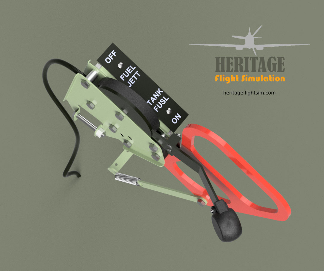
Our Mk.IX is thus fitted with a release mechanism which is situated to the right front of the seat on Frame 9. (the thingy with the red handle shown below:)

The mechanism includes a lever by which fuel flow from the external tank is controlled. While the lever is in the open position to the rear, it locks the red jettison handle into place. This can only be pulled when the lever is in the forward (closed) position, to prevent the fuel from the internal tanks from gushing out once the tank is released.


It would seem there were also bigger tanks available. A quote from Commander Crosley on the slipper tank fitted to Seafires indicates that these could carry 90 gallons, so were considerably bigger:
“Amongst the piles of ammunition, wireless sets, pilot’s seats, propeller spinners, tail steering arms, wing mats, sweating bodies and noise, we could see several huge slipper-shaped petrol tanks. Some of these were being offered up to the underside of the Spitfire’s fuselage — where a bomb might ordinarily be — and the fuel lines were being connected by an invisible, sliding fit. There was only a half-inch gap between the underside of the fuselage and the top surface of the tank, which was all of six feet long by two feet wide. We found that it could hold 90 gallons of 100 octane fuel. This was more than the Spitfire carried in its internal tanks. A closer study of the jettison arrangements showed that a Bowden cable release in the cockpit let go the lifting ring — stressed to three tons breaking strain — in the top surface of the tank. The tank then slid backwards onto two lugs sticking out two inches from the fuselage underside. The nose of the tank then dropped and the airflow forced it downwards and clear of the fuselage underside. The slightest skid, we thought, and the whole thing would come clear of the two lugs, slide back and hit the tail. However , the Spits would now have a range of 400 miles and would allow a fly-off to Malta well before we got to ‘bomb alley’.”
from http://www.armouredcarriers.com/seafire-variants/


For some other aircraft types such as the Mustang and Typhoon, the British invented paper tanks. Many hundreds of thousands of these were manufactured.

The following is a quote from Warbirdnews.com:
“Faced with wartime metal shortages, and a need to extend the range of fighter craft heading to Europe, the British came up with an ingenious design for auxiliary drop tanks, making them out of resorcinol glue-impregnated kraft paper, which while having excellent tolerance characteristics for extreme heat and cold necessary for operation on an aircraft as well as being waterproof, the glue would slowly dissolve from the solvent effects of the fuel contained within the tank, developing leaks within a few hours of being loaded with fuel, making them a strictly a one-time use item, filled right before takeoff.
The tanks were not considered robust enough to land a plane with them attached, so if a mission was scrubbed, pilots were required to drop their sometimes still-full tanks at a specified drop point, usually the airfield’s dump where the tanks would be jettisoned, though surprisingly we could not locate any cases where this caused a conflagration.”
http://warbirdsnews.com/warbird-articles/necessity-mother-invention-paper-drop-tanks-wwii.html
The coming update of DCS World Spitfire expected this month will incorporate slipper tanks.
“OK”
Said in Morse…
Morse code is now some 180 years old. When I saw the next item to be replicated for our Spitfire Mark IX was a Morse Code signal box, or “Switchbox Identification” in Air Ministry parlance, it gave pause for thought.
I could not help but wonder whether any pilot ever availed himself of this facility, given the effectiveness of spoken word radio communication by the 1940’s. Some research in Wikipedia soon illustrated that indeed, it was an extremely important means of communication.
Operators skilled in Morse Code can evidently often understand code in their heads at rates in excess of 40 words per minute (wpm). It is believed that some operators may have passed 100 wpm. By this time they are “hearing” phrases and sentences rather than words!
Operators also need to understand all the communications protocols, such as the abbreviations of the Q-Code. Many of those with an aviation background will recognise these, such as “QNH”, which is the barometric setting required to indicate the altitude of a specified location correctly.
So no doubt our aviators of the day were skilled or at least proficient in the use of Morse code. The Spitfire Mk.IX had two signal lamps, one mounted above the fuselage behind the cockpit and under mounted below. These were used when radio silence had to be maintained. It was thus essential to be able to communicate with the others in your squadron or on the ground with the signal box.
Thus it was a pleasure to replicate the original, using two three position switches, one each for the upper and lower lamps, and a morse key being a simple sprung pushbutton, all of which are operational in the DCS World Spitfire.

It will be great to practice my Morse skills on this. 🙂


Having completed the front of the cockpit things on the starboard side are beginning to take shape. As previously reported, the most complex component being the Chassis Control was completed and taking up the next spot is the Wobble Pump.

The wobble pump is used to build up fuel pressure before starting. In real life, when the handle of the wobble pump is operated, the negative pressure created on one side pulls upwards and lifts the lower flapper. This allows the fuel to flow behind it. As the handle is moved in the opposite direction, the lower flapper closes, preventing the fuel from escaping back into the line and forced through the upper flapper on the opposite side. The cycle is repeated each time the handle is moved in either direction.
In our case the lever is spring loaded and pushes against a microswitch each time the handle is pulled back. This signals its movement to the simulation engine. Typically the Spitfire would need around nine pumps of the handle to build sufficient pressure prior to startup.

In the meantime we have also been setting up our CNC router to engrave a number of Airscrew Control Levers for our limited quantity of Spitfire Mk.IX Engine Hand Control display units.

Here again we are doing the experimentation for you to get the font and positioning perfect. Our plan set includes the G-Code for either yourself or friendly CNC shop to engrave the lettering perfectly.
Here you can see the trail and terror prior to getting it just right 🙂

In the first example at the top we got the placement of the wording too far to the right and the lettering was also a standard TTF font, resulting in a double line. We then found a single line font and positioned it correctly, however as can be seen on the second example from the top this gave a fishtailing effect when run on engraving settings. Some research and we found we could run it on Trace instead of Engrave, giving the desired effect as shown on example three. The font however does not correspond to the original. The lower pile was done with the correct font. The cuts are made with a 60degree chamfer cutter, progressively with 0.2mm cuts down to 0.6mm, giving a letter width of just over 1mm. A last cut is given as a polishing cut. This is then sanded down and the process repeated, thus giving 8 cuts to provide the final result.
From here the levers will be bent and then powder coated in black prior to the lettering being applied in the grooves in white epoxy.
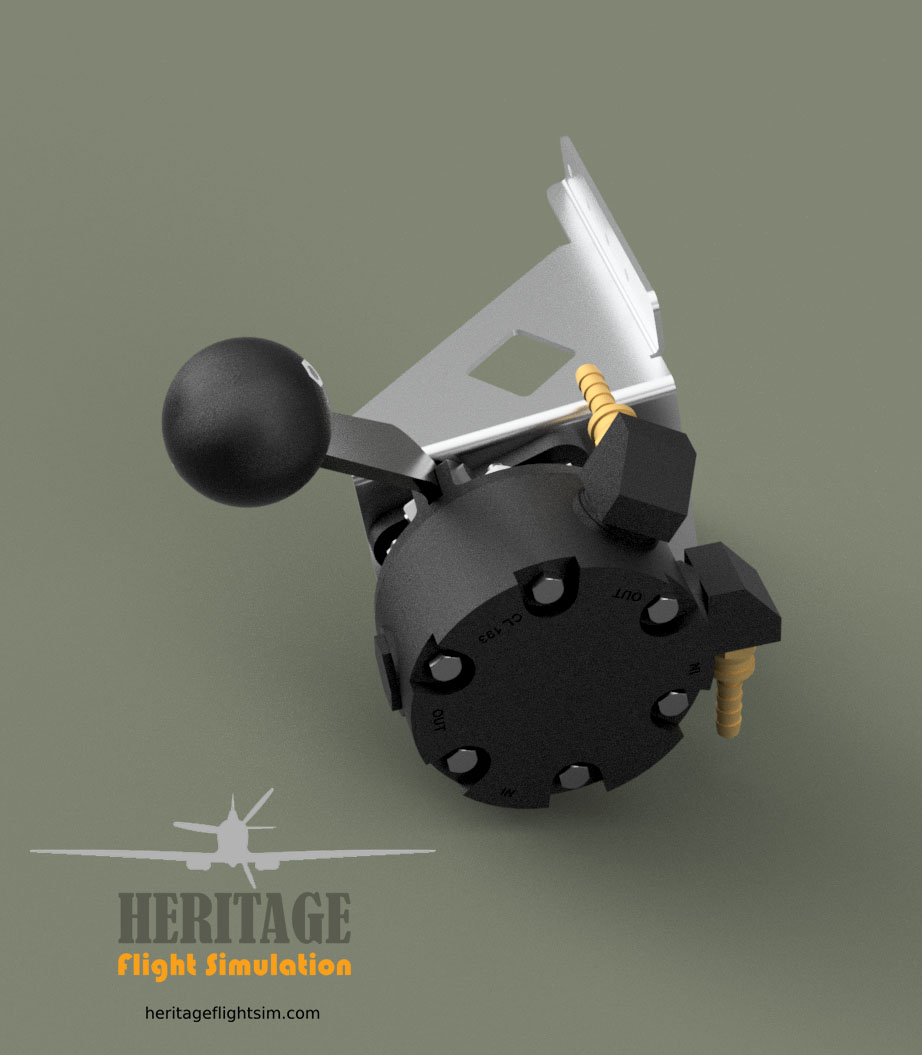
The controls below the instrument panel have been completed. These consist of the Main Fuel Cock, the KI-GASS Engine Fuel Priming Pump and the Fuel Tank Pressure Valve.

The Mk.IX had two tanks fitted in front of the instrument panel, an upper tank containing 48 gallons and a lower tank containing 37 gallons of 100 octane fuel. Fuel could run freely from the top to the bottom tank. The fuel flow from the lower tank to the engine fuel pump was controlled by the Main Fuel Cock located below the instrument panel to the right of the compass. In our case it provides interface to the simulation program by means of a simple toggle switch.


The purpose of the priming pump is to inject a fine spray of fuel into the air-intake of the engine for easier starting. The KI-GASS system was used on everything from the 1926 Vauxhall Tourer to diesel engined tractors.
It’s wonderful that the company still exists as Kigass Aero Components Ltd. in the UK and has been run by four generations of the Wardman family.
This interesting bit of equipment posed a few challenges to send the correct signals to the simulation software. The latter needs to be informed when the primer knob is unscrewed and then again when it is pumped. We solved this with some clever design and a simple toggle and micro switch.


The Fuel Tank Pressure Valve is used to reduce fuel vapourisation at high altitudes or temperatures which would result in an engine out.
Pressurizing, however, impairs the self-sealing of the tanks and should be turned on only when the fuel pressure warning lamp lights up. In very warm weather at very high altitudes a rich cut may occur with the tanks pressurized, and pressure must then be turned off.
The default position of the pressurizer system is OFF, and must be turned ON only when a red warning light signals that the fuel pressure has dropped below 10lb/in2.
Again operation is through a simple toggle switch.


It is worth noting that DCS World and many other simulators are not able to assess the initial start-up value of the switches, hence following a pre-startup checklist to normalise all switch positions is important to ensure correct function.

The design of the P8 Compass is complete. Our design incorporates a working top ring which turns a rotary encoder. This provides the required simulator interface while following the original design outline accurately.

I had the same compass installed in my Tiger Moth, No.82871. I must admit to cheating with SkyDemon on iPhone rather than trusting that ancient piece of equipment to guide the way!
Apparently it was designed for Naval use and not terribly precise as a navigational instrument in a fast moving fighter aircraft. There is a nice users guideline provided by the Air Combat Group.
It is such an iconic part of the RAF cockpit though, and I think our example came out really nicely!
Some more pics are available in the Gallery.
If a picture tells a thousand words, this must surely be it…


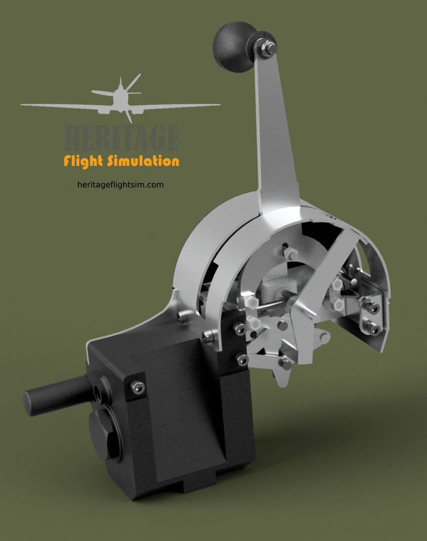
The Spitfire Chassis Control had, other than the name suggests, very little to do with it’s suspension. Instead it refers to the mechanism that activated the undercarriage. Perhaps the name was meant to convey its complexity, because complex it certainly is!
It is an array of hydraulic valves, pulleys and chains, which if by some stroke of dextrous genius the hapless pilot got right, would go clunking, whirring and rattling into place. Get it wrong and you would end up with a half retraction.
The manual describes the action required thus:
13. Undercarriage control.—The undercarriage selector lever (52) moves in a gated quadrant on the right-hand side of the cockpit. To raise the undercarriage the lever must be moved downwards and inwards to disengage it from the gate, and then moved forward smartly in one movement to the full extent of the quadrant.
When the undercarriage is locked up the lever will automatically spring into the forward gate.
Warning.—The lever must never be moved into either gate by hand as this will cut off the hydraulic pressure.
To lower the undercarriage the lever must be held forward for about two seconds, then pulled back in one movement to the full extent of the quadrant. When the undercarriage is locked down the lever will spring into the rear gate. An indicator in the quadrant shows DOWN, IDLE or UP depending on the position of the hydraulic valve. UP and DOWN should show only during the corresponding operation of the undercarriage and IDLE when the lever is in either gate. If, when the engine is not running, the indicator shows DOWN, it should return to IDLE when the engine is started; if it does not, probable failure of the hydraulic pump is indicated.
Our own design, which is progressing well, duplicates this action without the benefit of the hydraulics. We rely instead on a basic scissor spring action. It is set when the lever is moved downwards and inwards with a trigger plate. To move the lever inwards another spring (spring 2) needs to be compressed, as per the original mechanism. The lever is moved smartly forward, all in one movement, and then held in the foremost position for 8 seconds, the time in which the gear retracts. The lever is then released, causing it to snap outwards still under tension from spring 2. This activates the trigger release of spring 1 which snaps it back into the gate.
Quite simple. Heh heh…
You may of course elect to forego all that and do the build without the internals, having it operate simply as an up/down mechanism. But then, where’s the fun in that!


Today we installed the Radio Remote Control Box. The Type 4 (110J/71) control box operates the radio transceiver which is located in the rear of the fuselage. It has 4 preset channel buttons, labelled A, B, C and D. Next to each button is an indicator light showing which channel is active, The top button switches the remote off. At the bottom is a three way switch which is labelled “T-R-REM”. It toggles the three different modes of operation being Transceive, Receive and Remote.
In keeping with our philosophy to keep costs to a minimum, we have managed to utilise existing, readily obtainable components which closely match the look, function and size of the original.
Now to start on the Chassis Control Unit (gear lever)…bound to be an interesting challenge!
