Wobble Pump complete
Having completed the front of the cockpit things on the starboard side are beginning to take shape. As previously reported, the most complex component being the Chassis Control was completed and taking up the next spot is the Wobble Pump.

The wobble pump is used to build up fuel pressure before starting. In real life, when the handle of the wobble pump is operated, the negative pressure created on one side pulls upwards and lifts the lower flapper. This allows the fuel to flow behind it. As the handle is moved in the opposite direction, the lower flapper closes, preventing the fuel from escaping back into the line and forced through the upper flapper on the opposite side. The cycle is repeated each time the handle is moved in either direction.
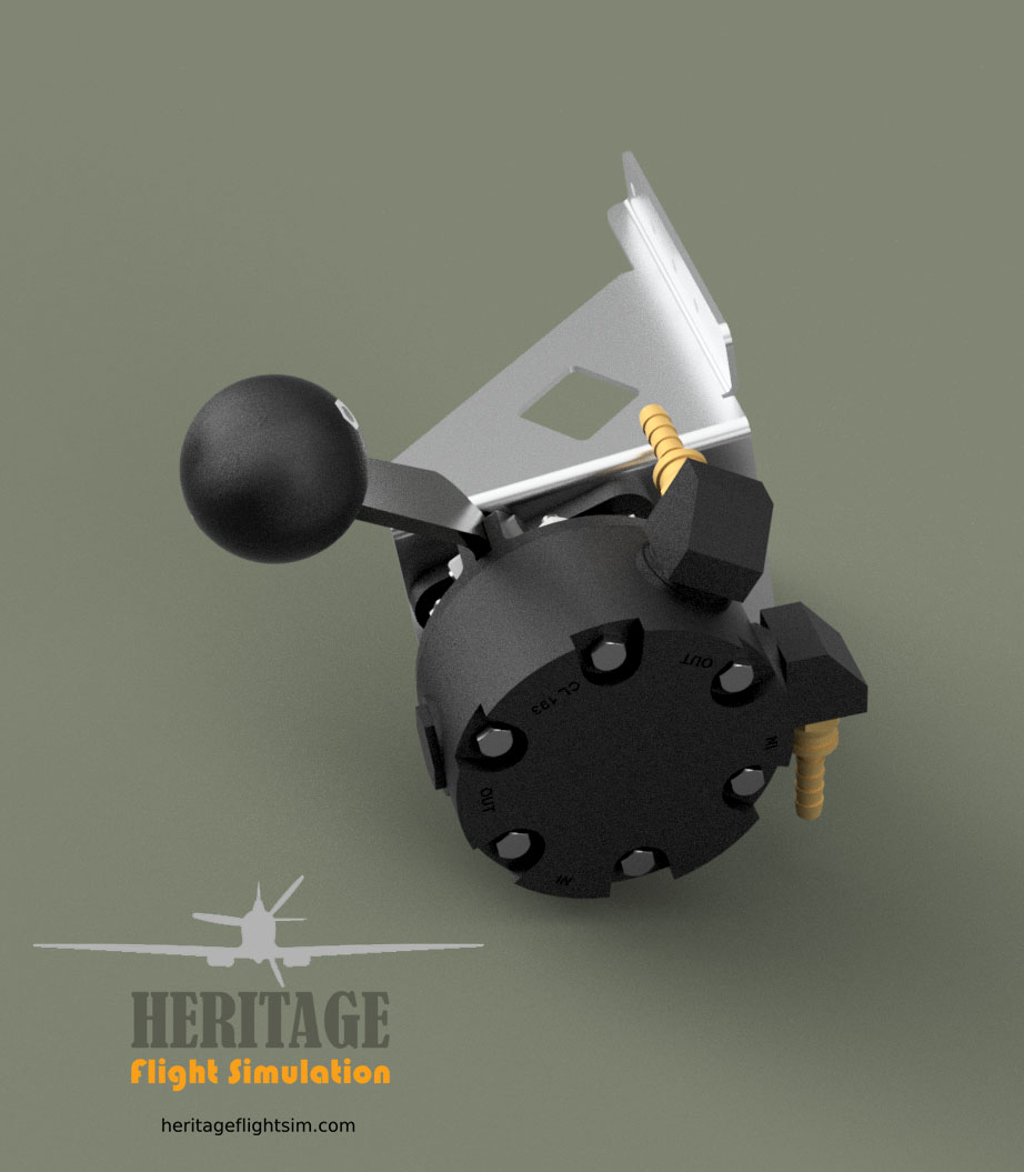
In our case the lever is spring loaded and pushes against a microswitch each time the handle is pulled back. This signals its movement to the simulation engine. Typically the Spitfire would need around nine pumps of the handle to build sufficient pressure prior to startup.

Cutting Grooves
In the meantime we have also been setting up our CNC router to engrave a number of Airscrew Control Levers for our limited quantity of Spitfire Mk.IX Engine Hand Control display units.

Here again we are doing the experimentation for you to get the font and positioning perfect. Our plan set includes the G-Code for either yourself or friendly CNC shop to engrave the lettering perfectly.
Here you can see the trail and terror prior to getting it just right 🙂

In the first example at the top we got the placement of the wording too far to the right and the lettering was also a standard TTF font, resulting in a double line. We then found a single line font and positioned it correctly, however as can be seen on the second example from the top this gave a fishtailing effect when run on engraving settings. Some research and we found we could run it on Trace instead of Engrave, giving the desired effect as shown on example three. The font however does not correspond to the original. The lower pile was done with the correct font. The cuts are made with a 60degree chamfer cutter, progressively with 0.2mm cuts down to 0.6mm, giving a letter width of just over 1mm. A last cut is given as a polishing cut. This is then sanded down and the process repeated, thus giving 8 cuts to provide the final result.
From here the levers will be bent and then powder coated in black prior to the lettering being applied in the grooves in white epoxy.